2-Day Expedited Shipping Only $14.95 - See Restrictions
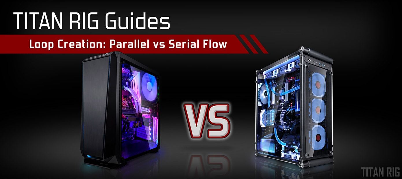
PC Guides - Serial vs Parallel Flow
December 06, 2021 13
So you’re building a new custom water cooling system. You’ve chosen all your components carefully with the help of our guides. They’re all going to fit within your space and work nicely together. You’ve got a place to mount everything and you’re just about ready to start the hands-on part. All that’s left is planning your tube routing.
I’ve heard people say that tube routing isn’t that important, but the way your tubing is plumbed affects not only how much tubing you’ll need, but how many fittings, how much coolant, how hard your pump will have to work, and how the end product looks.
The first question I typically see about tube routing is loop order. That one’s easy as it’s been proven repeatedly that as long as the pump is being fed coolant directly from the reservoir, loop order doesn’t matter. You can run your coolant through all your water blocks and then your radiators, or put a radiator between each block and your temps will not be measurably different. Seems counterintuitive at first but it’s true.
The next question is often about parallel loops. People see them and the question is usually “How can I make one like that?” or “How in the world does it work?”
What Is It?
There are two ways to plumb your loop: in series or in parallel. There are sub-categories here like series-parallel but those typically only apply to the largest and most complex water loops.
Series loops are the simplest and most common. In a series loop, coolant is fed to your water cooling components one at a time. A typical loop order might be reservoir-pump-GPU block-CPU-block-radiators-reservoir. One at a time in line until the coolant circles back to start the trip again.
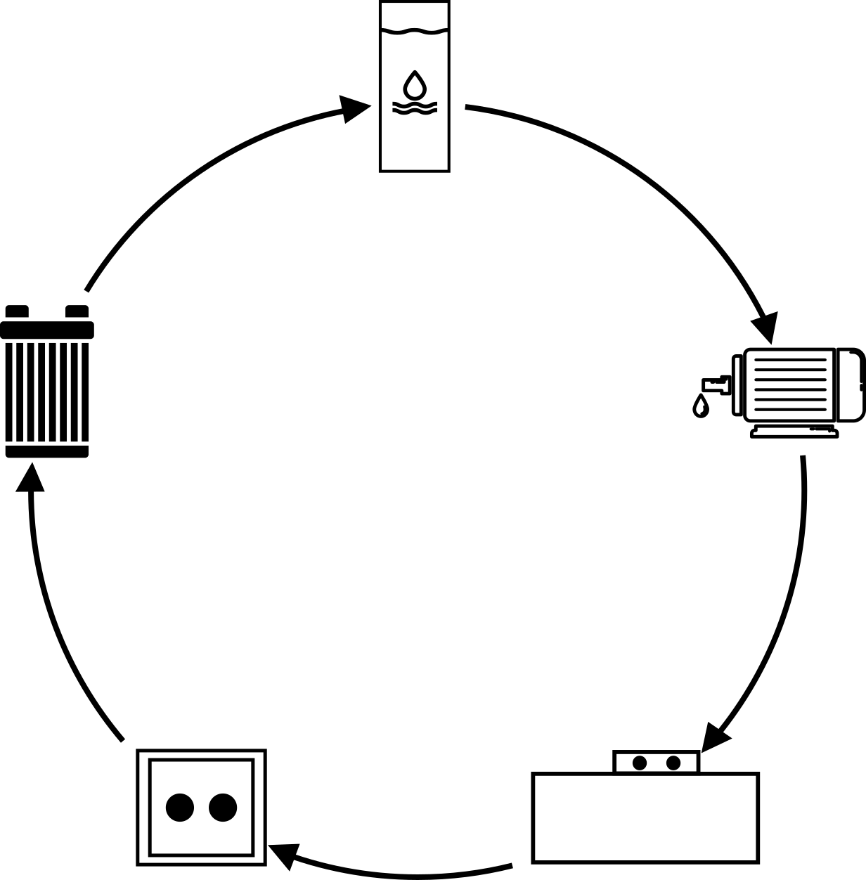
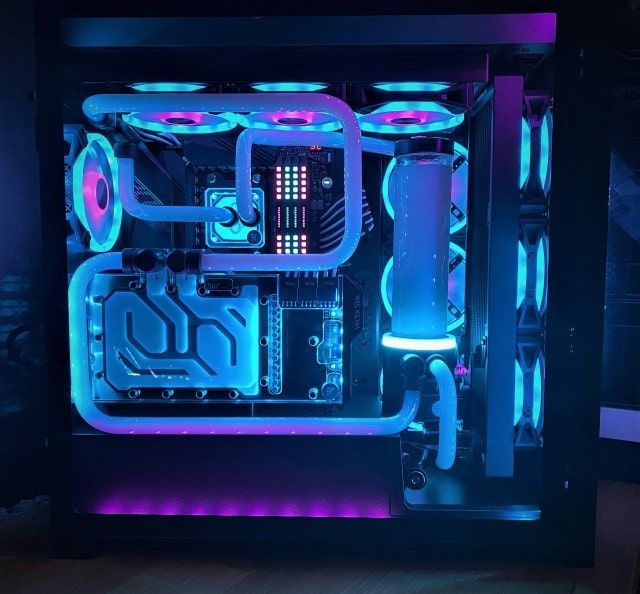
Image credit: Redditor /u/kingtruff88
Parallel loops split the flow of coolant temporarily in the middle of the loop. The most common way it’s done is by splitting the flow at the GPU block.
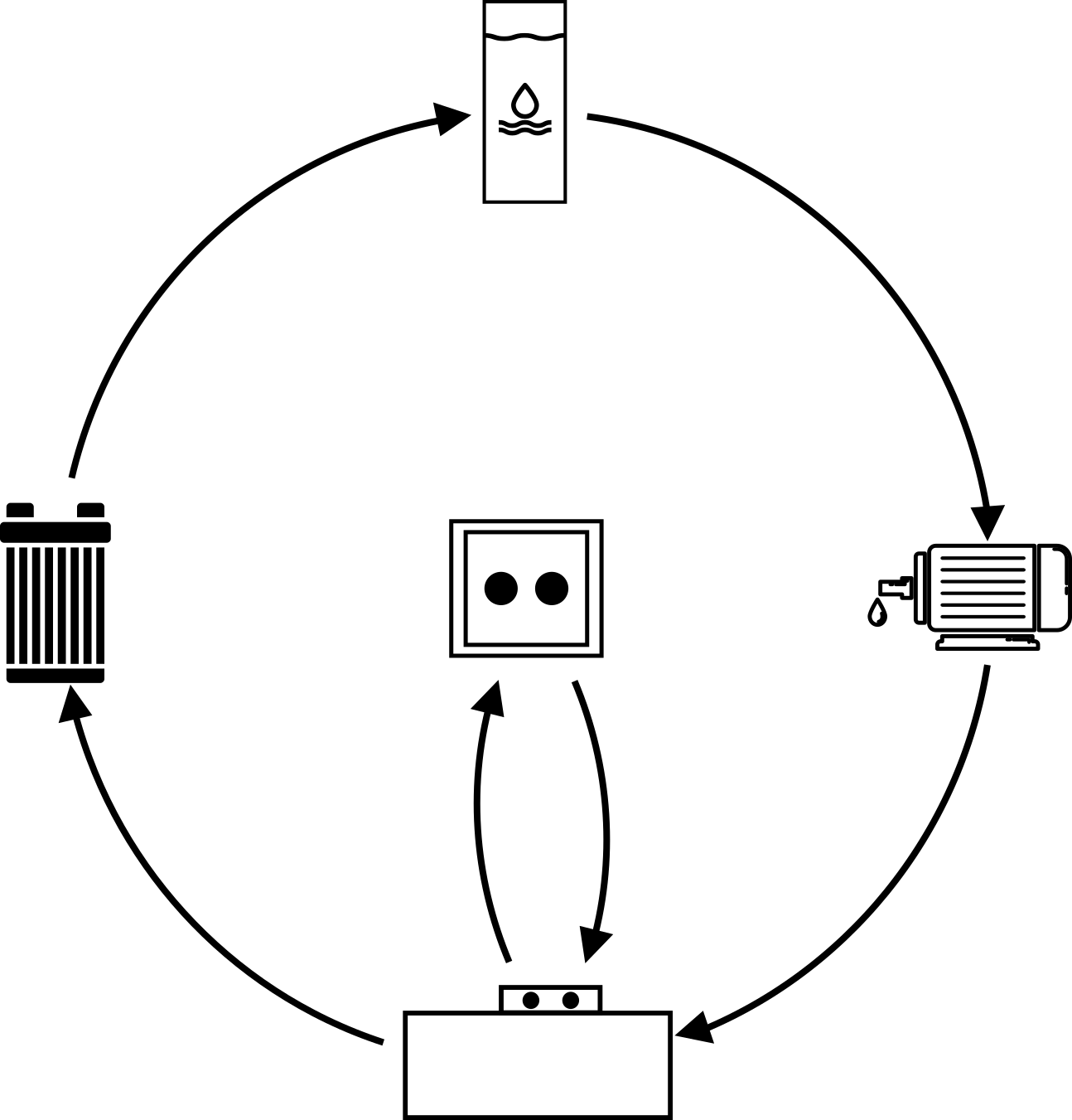
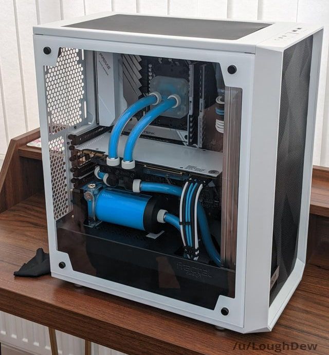
Image credit: Redditor /u/LoughDew
Parallel tube routing is done for aesthetics and to make routing easier. It eliminates the long run usually seen either entering or exiting the CPU block.
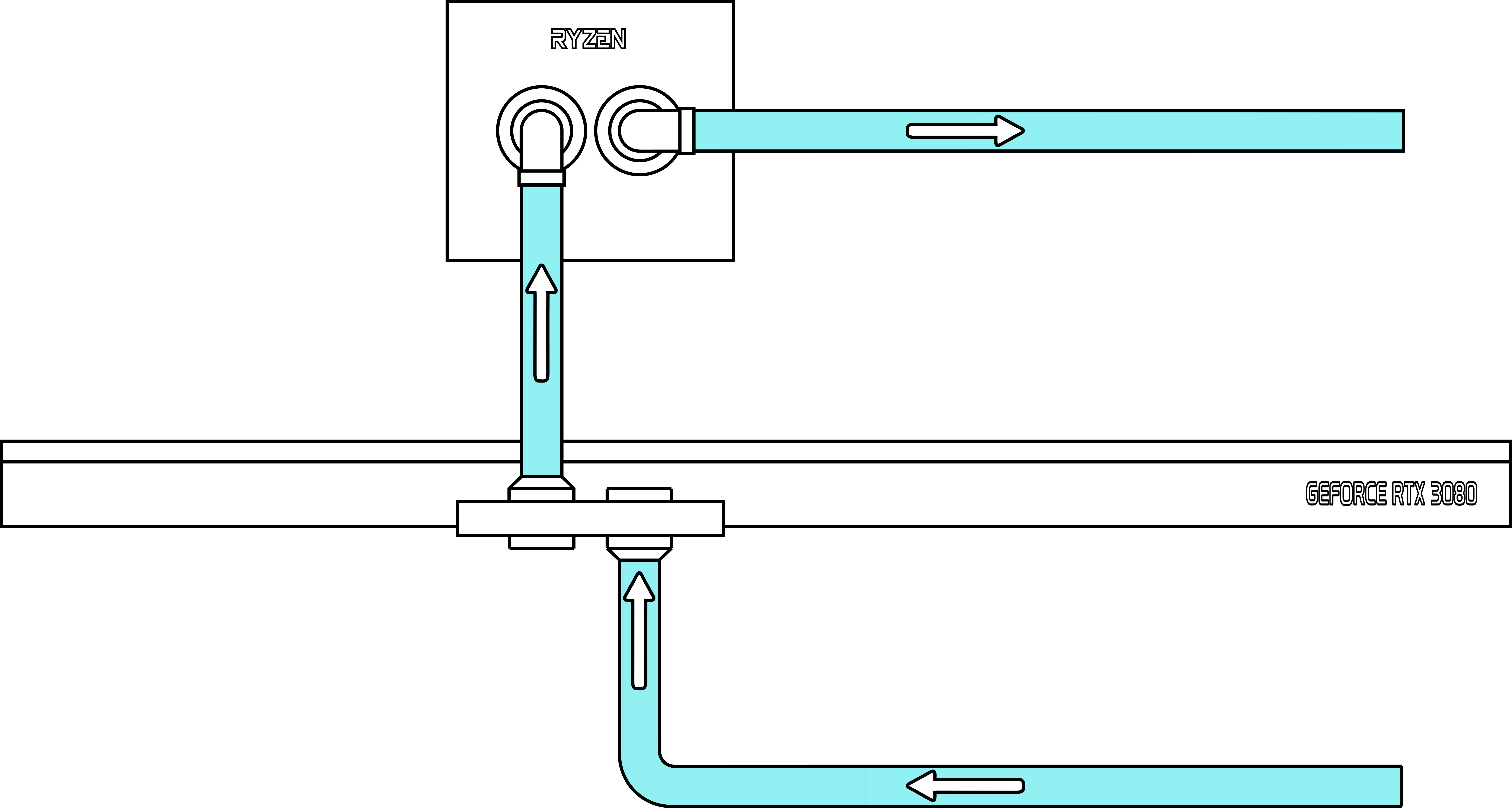
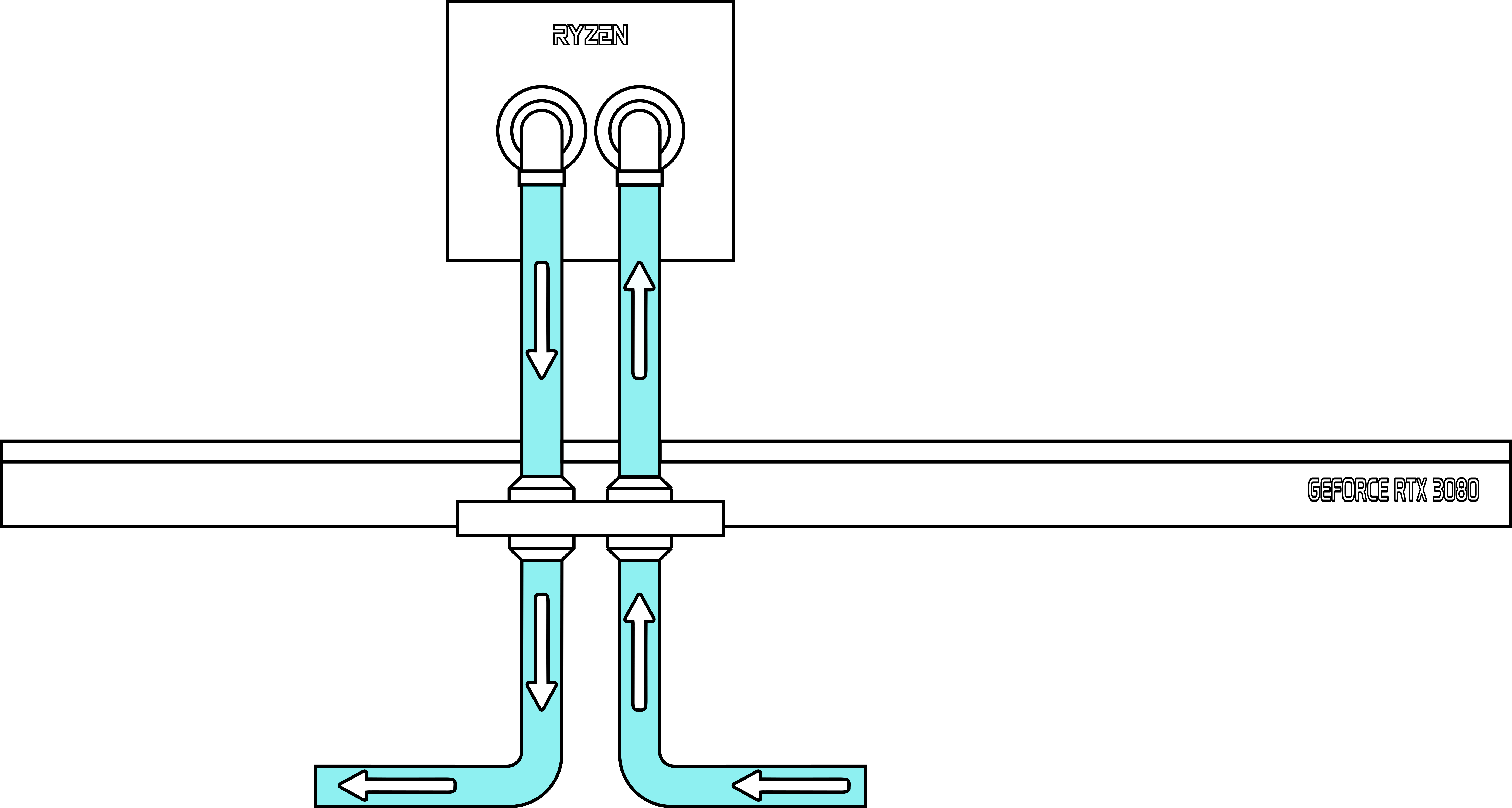
Series flow Parallel flow
How Does It Work?
Parallel flow is simple to execute, but if you look at the flow of the coolant into and out of the graphics card block, it looks like it would just shoot right through the holes where the fittings are attached and not circulate inside the block to cool anything down. Common sense says that with equal pressure on both sides of the water block, nothing would flow through it.
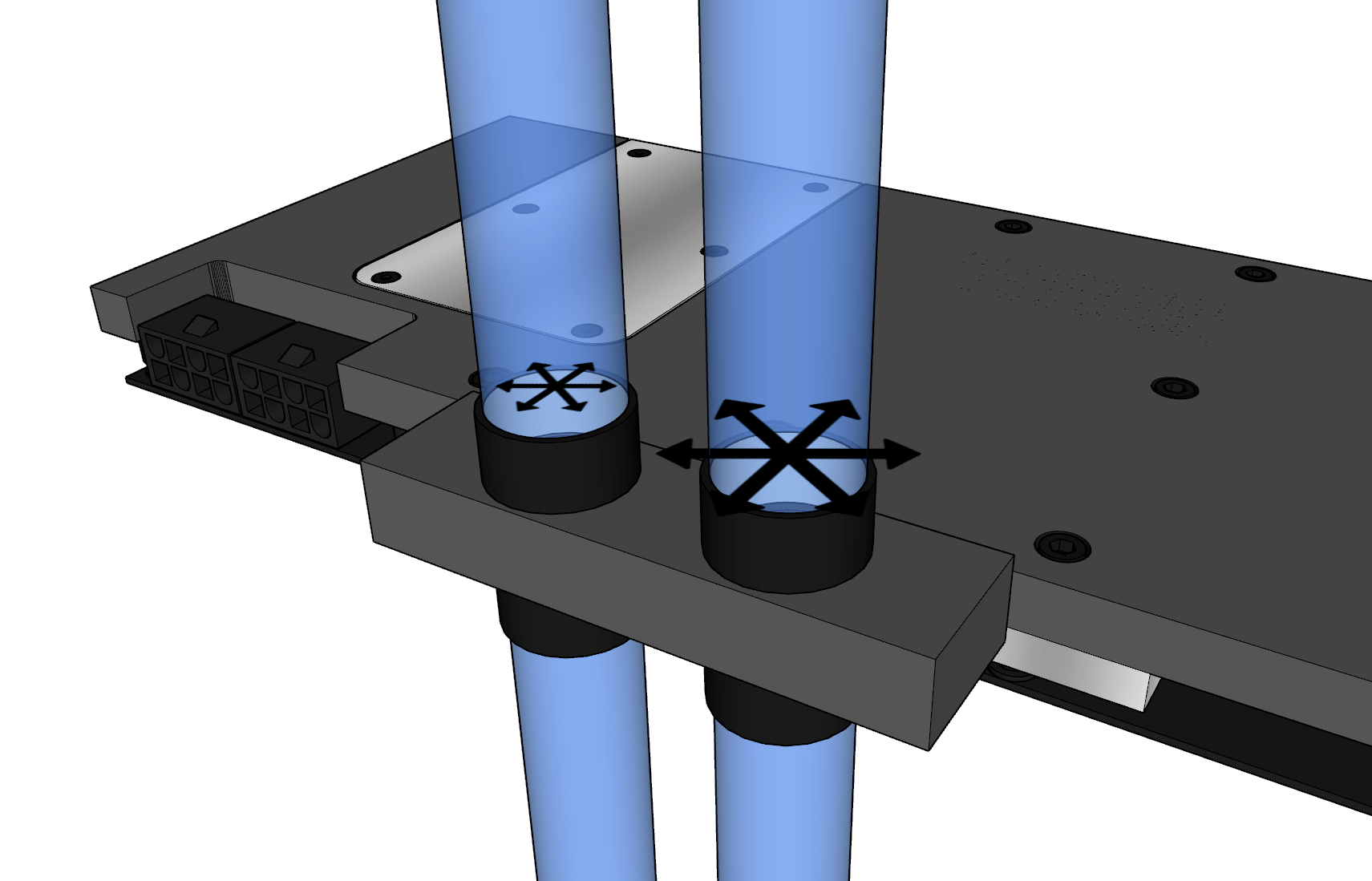
In fact, that’s absolutely true. Thankfully in these setups the pressure on the inlet and outlet sides of the graphics card water block is NOT equal.
Let’s say that the coolant flowing through the inlet port of the VGA block and up to the CPU block is at X amount of pressure. Measure it in PSI, millibars, muppets – the unit doesn’t matter.
As it passes through the CPU block we get a pressure drop. Passing through any restriction will cause a pressure drop in the fluid.
So, the coolant flowing through the outlet port of the VGA block is *less than X* amount of pressure. That gives is a pressure differential across the video card block, which causes flow.
Realizing that, the amount of restriction caused by the CPU block will affect the flow across the VGA block, though its effect will be minimal.
Putting It To The Test
I decided to put the two flow patterns to the test to see how much difference they made. For my testing, I used the following components:
PC Hardware
Mainboard: MSI B85-G43 Gaming
CPU: Intel i7-4690K
GPU: GeForce GTX Titan
Memory: 16GB (8x2) Patriot Viper DDR3
PSU: Phanteks AMP 650-watt
Case: Modified Raijintek Paean
Water Cooling
Pump: EK D5 PWM with EK XTOP Revo
Reservoir: Barrow 300mm tube
Radiator: BarrowCH Chameleon Fish 360mm
Fans: Arctic P12 PWM fans (x3)
VGA Block: EK-FC Titan Nickel/Acetal
CPU Block: Phanteks Glacier C350i
Fittings: XSPC 3/8” barbs
Tubing: EK Duraclear 3/8” – 5/8” flexible
Coolant: Distilled water
The first test was done with the tubing in series configuration.
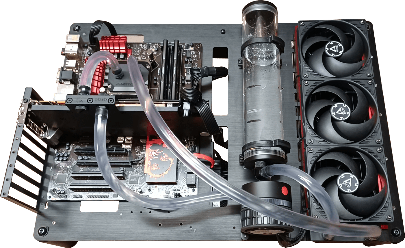
Titan Rig’s Bleeding-edge testing setup plumbed for series flow.
To start the test, I let the system idle for an hour. The reservoir I used holds a lot of water and takes a while to reach thermal equilibrium.
Once a steady state had been reached, I started AIDA64 and Open Hardware Monitor. To stress the system I used AIDA64’s native System Stability Test to load the CPU and GPU to 100% and kept them there for an hour.
After stressing for an hour in series configuration, I shut the system down, drained the coolant and changed the tubing to a parallel setup.

Plumbing changed for parallel flow.
I repeated the test as before, including the initial warm-up period.
Test Results
In both tests the CPU and GPU temps climbed slowly at first as expected but leveled out before the test ended. I saw no reason to think that they would climb beyond that range.
Series: CPU max temp – 51.5C GPU max temp – 36.5C
Parallel: CPU max temp – 54.5C GPU max temp – 38.5C
The change in tube routing resulted in a 3-degree increase in max CPU temp and a 2-degree difference in max GPU temp at 100% load. As with any testing, these results are particular to this test setup. Your choice of CPU block as well as your other components, ambient temps, air flow etc. will produce different results. Your mileage may vary.
When the testing was done I decided to run one more test in an effort to confirm or disprove my theory on pressure drop causing flow. I removed the CPU block from the loop and installed an air cooler on the CPU, and then ran a simple bypass loop between the two upper GPU ports.

Let’s test this theory….
This is still a parallel-flow setup, but the bypass loop takes the place of the CPU block. My thought was to minimize the pressure drop between the outlet and inlet ports and see if it affected the flow inside the VGA block. If my theory was right, I should see increased temperatures on the VGA core due to reduced flow, caused by the reduced pressure differential.
The results: Max GPU temp was 39C – .5 degrees higher. Not what I had expected at all.
There are a few possibilities for the unexpected outcome.
1: The bypass loop still provides enough pressure drop to promote flow across the ports
2: My cooling solution is too efficient for lower flow across the block to result in increased temperatures
3: I’m completely wrong about pressure drop and pressure differential causing flow through the block and I’m back to not understanding what causes it
If any of you have any other ideas as to why my GPU temps weren't much higher as I expected them to be, let me know in the comments!
I’d like to perform this test again in the future with pressure and flow meters in key areas of the loop just to be certain of the results. Until then….
Given the test results, I can confirm what I’d heard secondhand regarding parallel flow: performance will suffer but not by much. If you like the aesthetic of parallel tube routing and you’re willing to give up a few degrees of cooling performance – go for it!
13 Comment(s)
Load more comments
Recent Posts